This guide explains the part number structure and geometry codes used for UPT wedge wire bonding tools — including small wire, heavy wire and ribbon wedge series. Ball bonding capillaries and other product lines use separate numbering systems; please refer to their respective product pages or contact us.
Geometry Reference
Below is an example of a typical wedge bonding tool part number. Hover over each segment to see what it defines.
1 Material
The first position defines the tool material: P = Cermet, W = Tungsten Carbide, T = Titanium Carbide. For additional materials, refer to the Material Selection Guide.
2 Series
The series defines the tip geometry and bonding foot profile, including front and back configuration. See the Series Configuration Table.
3 Wire Feed
Defines the wire feeding configuration of the bonding tool. O = Standard Feed, V = Vertical Feed.
4 Front / Back Radius
Defines the front and back radius of the bonding foot, which determine the transition of the bond and heel region. See the Radius Option Chart for available options.
5 Shank Diameter
Defines the diameter of the tool shank. The standard shank diameter for small wire tools is 1/16 in.
6 Tool Length
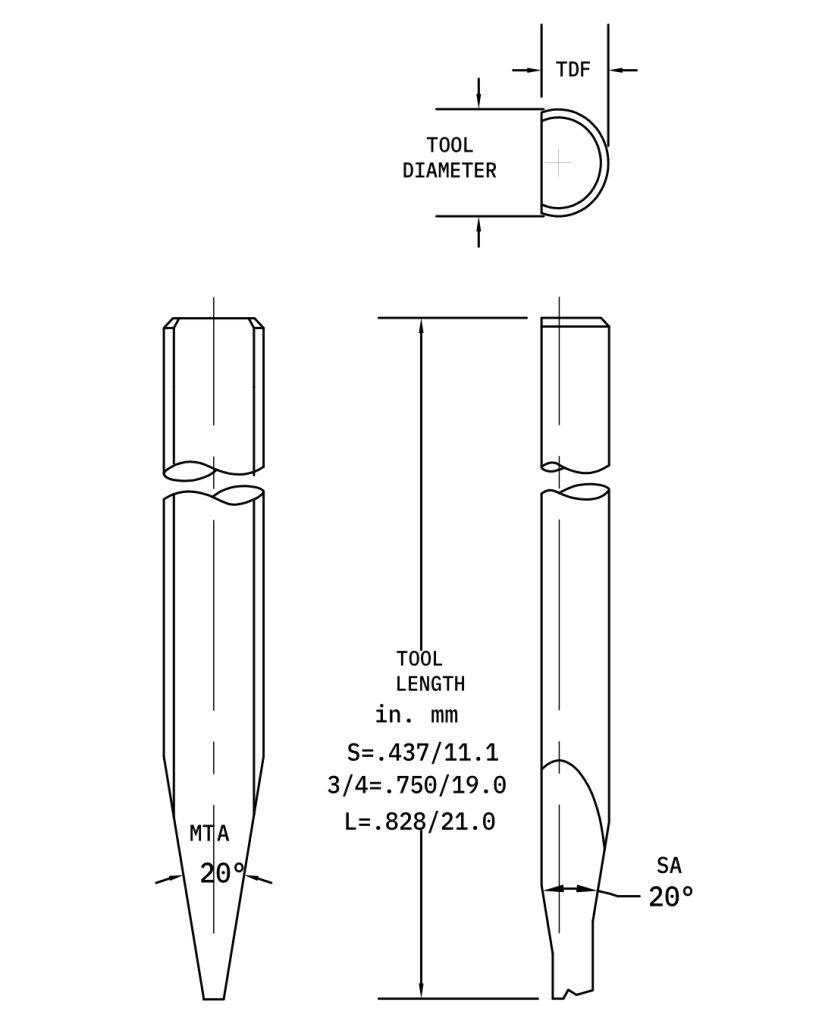
Defines the overall length of the bonding tool. The value corresponds to the tool length in inches (e.g., 1 = 1.000 in, 750 = 0.750 in).
7 Hole Angle
Defines the angle of the wire hole in the bonding tool. Common options include 30°, 45°, and 60°.
8 Foot Type
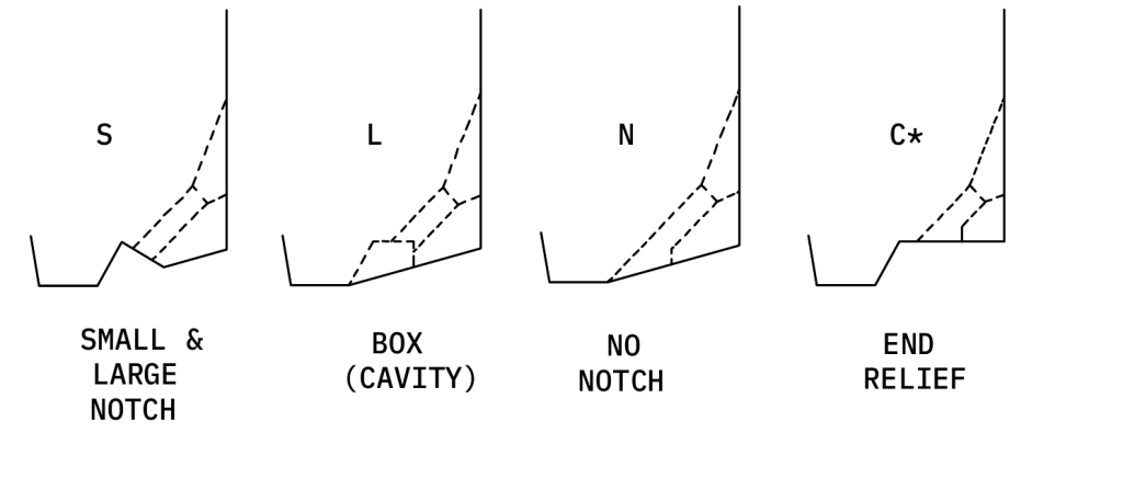
Defines the bonding foot geometry of the tool. Common types include F (Flat), C (Concave), CSF (Concave with Side Flats), GW (Groove in Wire Direction), VG (V-Groove), and CG (Cross Groove). See the Foot Type Diagram for detailed configurations.
9 Tool Size
Defines the bonding tool size using a TS code. The Standard Tool Size Chart lists the corresponding dimensions, including hole diameter (H) and bond length / foot length (BL).
10 Foot Finish
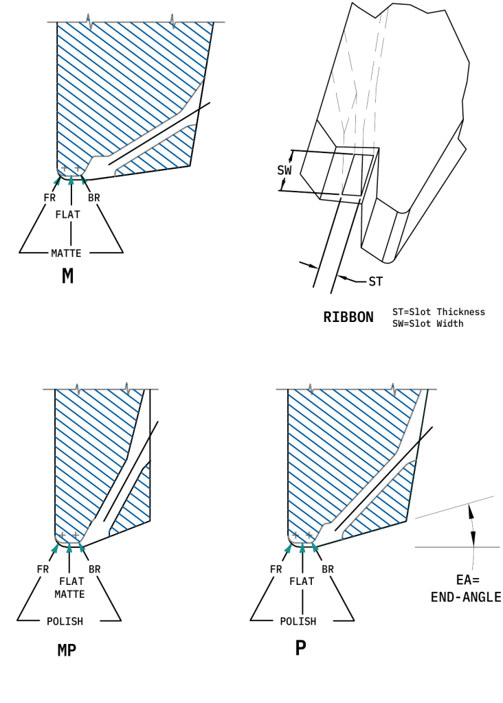
Defines the surface finish of the bonding foot. Available options include M (Matte), MP (Matte + Polish), and P (Polish). Refer to the Foot Finish Diagram for details.
11 Tool Options
Specifies optional tool modifications for special bonding conditions. Refer to the Tool Options Chart for typical examples. For specific requirements, please consult our engineering team for customized solutions.
Radius Option Chart
Radius Option Chart front / back radius combinations by option letter
| Option Letter | A | B | C | D | E | F | G | H | I | J | K | L | M | N | |
|---|---|---|---|---|---|---|---|---|---|---|---|---|---|---|---|
| FR | mil | 0.5 | 0.5 | 1.0 | 1.0 | 1.0 | 1.5 | 1.5 | 1.5 | 1.5 | 2.0 | 2.0 | 2.0 | 2.0 | 2.0 |
| µ | 13 | 13 | 25 | 25 | 25 | 38 | 38 | 38 | 38 | 51 | 51 | 51 | 51 | 51 | |
| BR | mil | 0 | 0.5 | 0 | 0.5 | 1.0 | 0 | 0.5 | 1.0 | 1.5 | 0 | 0.5 | 1.0 | 1.5 | 2.0 |
| µ | 0 | 13 | 0 | 13 | 25 | 0 | 13 | 25 | 38 | 0 | 13 | 25 | 38 | 51 | |
FR = front radius · BR = back radius. The option letter is specified in position 4 of the part number. Example: option D = FR 1.0 mil (25 µm) with BR 0.5 mil (13 µm).
Application Matrix
Every series mapped to wire material, feed style, and package access. Locate your application in the columns, then read across to the matching series.
Standard / recommended Available / on request
| Series | Front | Back | Foot | Feed | Au | Al | Deep access | Fine pitch | Power pkg |
|---|---|---|---|---|---|---|---|---|---|
| CHAPTER 1 · SMALL WIRE WEDGE TOOLS | |||||||||
| RA | SF | BA | L | O · V | ● | ● | |||
| RB | SF | BA | N | O · V | ● | ● | ○ | ||
| RC | SF | BA | S | O · V | ● | ● | |||
| JA | SF | BS | C | O · V | ● | ● | ● | ○ | |
| JB | SF | BS | L | O · V | ● | ● | |||
| JC | SF | BS | N | O · V | ● | ● | ● | ○ | |
| JE | SF | BS | S | O · V | ● | ● | |||
| CA | FA | BS | N | O · V | ● | ● | ● | ● | |
| CB | FA | BS | L | O · V | ● | ● | |||
| CC | FA | BS | S | O · V | ● | ● | ● | ● | |
| JBH | SF | BS | L | O · V | ● | ● | ● | ○ | Double-flat wire tool |
| CHAPTER 2 · RIBBON WIRE TOOLS | |||||||||
| JD | Ribbon wedge · std & vertical feed | O · V | ○ | ● | ○ | ||||
| JDH | Ribbon wedge · fixed feed | O · V | ○ | ● | ○ | Double-flat wire tool | |||
Part Number Structure
Dimensions measurement symbols used on tool profiles and size charts
| Symbol | Name | Applies | Symbol | Name | Applies | Symbol | Name | Applies |
|---|---|---|---|---|---|---|---|---|
| TS | Tool size code | W | WD | Wire diameter | W · C | CD | Chamfer diameter | C |
| H | Hole diameter | W · C | TL | Tool length (overall) | W · C | CA | Cone angle | C |
| BL | Bond length | W | SD | Shank diameter | W · C | ICA | Inner chamfer angle | C |
| D | Tip diameter (at foot) | W | HA | Hole angle (feed) | W | OR | Outer radius | C |
| T | Foot / tip width | W · C | FR | Front radius | W | BNH | Bottleneck height | C |
| W | Foot length | W | BR | Back radius | W | BNA | Bottleneck angle | C |
Applies to: W = wedge tool · C = ball bonding capillary
Tool Configuration Codes feature codes appearing in tool part numbers
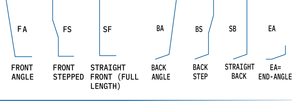
Front Profile
| SF | Straight front |
| FA | Front angle |
| FS | Front step |
Back Profile
| SB | Straight back |
| BA | Back angle |
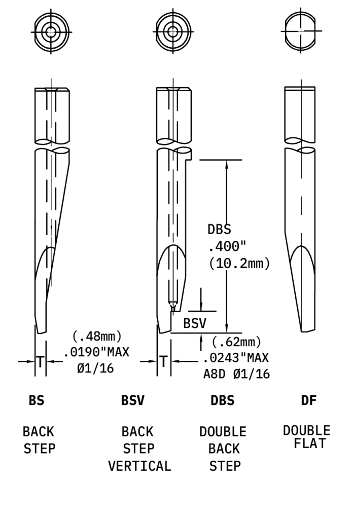
| BS | Back step |
| BSV | Back step, vertical |
| CBR | Chamfered back radius |
| DBS | Double back step |
Bond Features
| BF | Bond flat |
| LR | Left radius |
| RR | Right radius |
Foot Profile
| N | No notch |
| S | Small notch |
| R | Regular notch |
| L | Box (cavity) |
| C | Concave foot |
| C* | End relief |
| C/CG | Concave with cross groove |
| CG | Cross groove |
| VG | V-groove |
| VGC | Chamfer on V-groove |
| GW | Groove in wire direction |
Surface Finish
| M | Matte |
| MP | FR & BR polished, BF matte |
| P | Polished |
| ECM | Extra coarse matte |
Feed
| V | Vertical feed |
Special Features
| BC | Back chamfer |
| CM | Center of mass |
| DF | Double flat |
| ELG | Elongated hole |
| SC | Side chamfer |
| SS | Side step |
| TD | Tool diameter |
| TDF | Tool diameter flat |
Material Codes first position of the part number
Solid Tools
| C | Tungsten carbide (6% cobalt) — standard |
| Z | Zirconia |
| N | Titanium nitride |
| R | Roctec |
| F | Cobalt-free tungsten carbide |
| 2 | GO2 2010 (10% cobalt, light) |
| TS | Solid titanium carbide |
Welded Tools (tip / shank)
| M | Ceramic / tungsten carbide |
| L | Zirconia / tungsten carbide |
| B | Titanium diboride / tungsten carbide |
| Y | Tungsten carbide / zirconia |
| G | Ceramic / zirconia |
| J | Titanium diboride / zirconia |
| I | Ceramic tip, zirconia insulator, carbide shank |
| E | Ceramic tip, non-electrical insert, carbide shank |
| T | Titanium tip / carbide shank |
Code Glossary
Foot Finish
Tool Dimensions
Vertical Feed Styles
Front & Back Profile
Front profile codes (FA · FS · SF) define the leading face; back profile codes (BA · BS · SB · EA) define the heel side.
Foot Profile