
This guide explains the part number structure, groove geometries and configuration options for UPT heavy wire wedge tools (AFK series), used for heavy aluminum and copper wire bonding in power packaging. Small wire and ribbon wedge tools use a different coding system — see the Wedge Tool Part Number Guide.
Part Number Structure
Below is an example of a typical heavy wire wedge tool part number. Hover over each segment to see what it defines.
1 Material
The first position defines the tool material. W = Tungsten Carbide is standard for heavy wire tools. For additional materials, refer to the Material Selection Guide.
2 Series
Available with V-groove or G-groove foot profiles. See the Groove Geometry section below.
3 Shank Diameter
Defines the diameter of the tool shank. The standard shank diameter for heavy wire tools is 1/8 in.
4 Tool Length
Defines the overall length of the bonding tool, tuned to match the bonder’s ultrasonic frequency.
5 Wire Diameter
Defines the wire size the tool is configured for. Wire diameter determines groove dimensions and bonding energy coupling.
6 Front / Back Radius
Option letter defining the front and back radius combination of the bonding foot. FR sits opposite the wire guide; BR on the guide side. See the Radius Option Chart.
7 Foot Finish
Defines the surface finish of the bonding foot. Available options include M (Matte), MP (Matte + Polish), and P (Polish).
Application Matrix
Chapter 4 · H series selection
| Series | Groove | Al | Cu | Std FL/D |
Customized FL/D |
Power pkg |
|---|---|---|---|---|---|---|
| HG | U-groove | ● | ● | ○ | ● | |
| HV | V-groove 60° | ● | ● | ● | ○ | ● |
| HV7 | V-groove 70° | ● | ● | ● | ○ | ● |
| HV7D | V-groove 70°, for F&K Delvotec | ● | ● | ● | ○ | ● |
| HV7S | V-groove 70°, Side-Angle | ● | ● | ● | ○ | ● |
● standard configuration · ○ available on request. FL/D = foot length to wire diameter ratio — see the Heavy Wire Tool Guide for foot length design options.
Key Parameters
what defines a heavy wire tool configuration
Wire Diameter
Defines tool size and bonding energy
Bonding Frequency
Determines ultrasonic system matching
Tool Length
Tuned to match machine frequency
V-Groove Geometry
Controls wire stability and energy transfer
Foot Length (FL)
Affects bond size and reliability
Front Cut & Rear Cut
Defines accessibility and process flexibility
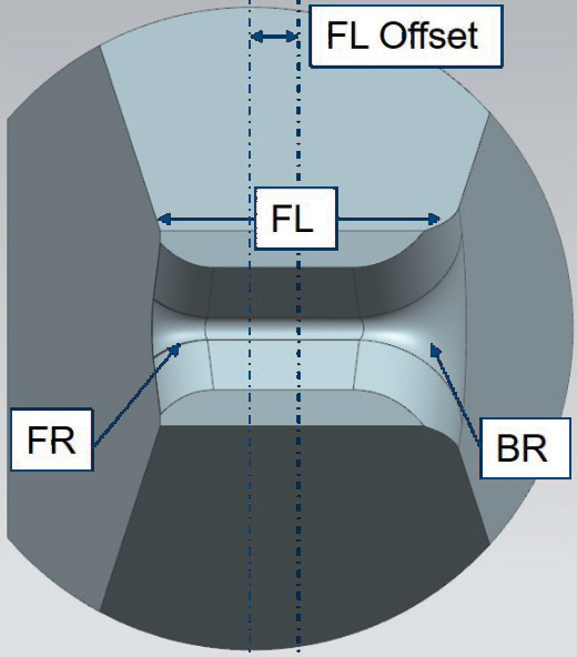
Tool Specification Structure dimension symbols

L : Length of Tool
FL : Foot length
FL Offset : Distance between center of foot and center of rod.
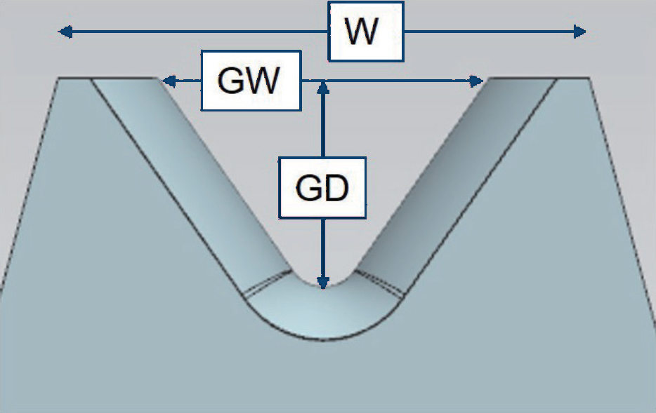
W : Width of tool
GW : Groove width
GD : Groove depth
FR : Front radius (opposite to guide)
BR : Back radius (on the guide side)
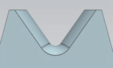
Groove Geometry V-groove vs G-groove
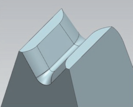
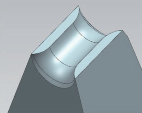
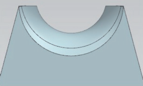
V-Groove
G-Groove
Classic heavy-wire capture geometry. The V profile centers the wire and couples ultrasonic energy across the full diameter range.
Rounded groove profile providing an alternative contact geometry for wire capture and deformation control.
Foot Length Design FL/D ratio options
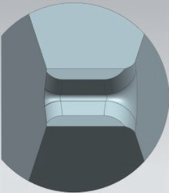
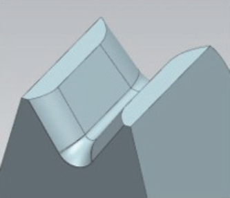
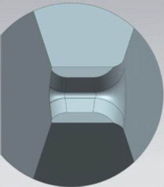
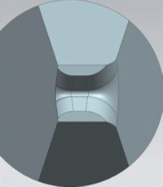
Standard foot length design FL/D ≈ 3 suits most applications. Shorter designs (FL/D = 2.5 or 2) are commonly used for limited clearance or confined bonding areas; longer foot geometries (FL/D = 4) apply when extended bond lengths are required.
FL/D = 3
Balanced bonding performance — the default choice

FL/D = 2.5
For limited clearance areas
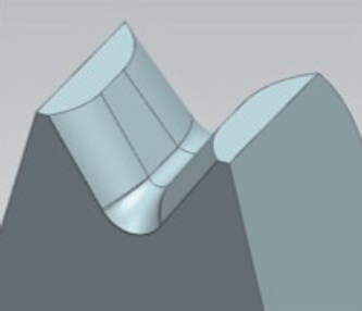
FL/D = 2
For confined bonding areas
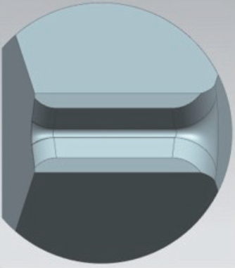
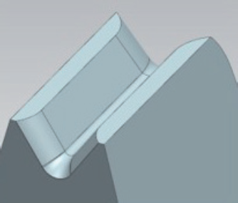
FL/D = 4
When extended bond lengths are required
Front Cut & Rear Cut Design bond head configurations
Heavy wire wedge bonding systems are commonly available in two bond head configurations. In a front cut design, the cutter is positioned in front of the bonding tool; in a rear cut design the cutter is located between the bonding tool and the wire guide assembly.
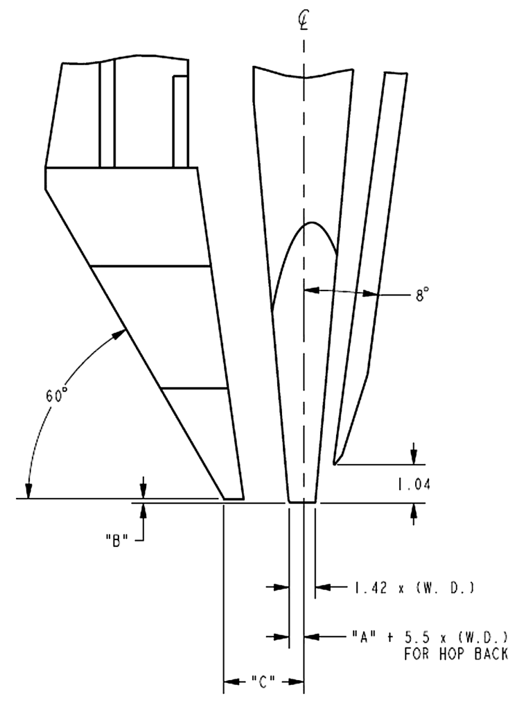
Front Cut
- Simpler wire termination process
- Widely used for standard bonding applications
- Suitable for open bonding areas with sufficient clearance
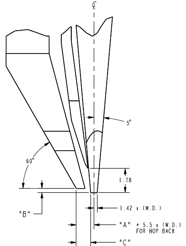
Rear Cut
- Improved front-side clearance for deep access applications
- Reduced risk of contact with sensitive device surfaces
- Preferred for bonding close to package walls, ledges, or adjacent components
Rear cut configurations are commonly used in applications requiring enhanced accessibility or bonding on sensitive active areas. Specify your bond head configuration when ordering.