
UPT tungsten carbide tips are engineered for inverted-pyramid and inverted-channel die profiles, built on our own part numbering system across four shank structures. Each part number encodes the shank, tool length, material and tip geometry in a single string, so you can read off the full specification from the code itself.
Tungsten Carbide · 4 Shank Structures · Inverted Pyramid & Channel Die Profiles
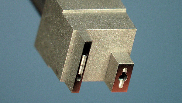
How to Read a UPT Tungsten Carbide Tip Part Number
UPT tungsten carbide tips use two related part numbering formats, depending on tip structure. Both start the same way — shankdiameter, shank structure, tool length and material — then diverge to describe the tip geometry itself.
Format 1 — General Tip Structure
Below is an example of a typical tungsten carbide tip part number. Hover over each segment to see what it defines.
1 Shank Diameter
Defines the diameter of the tool shank. 2 = 1/8 in = 3.175 mm.
2 Shank Structure
Defines the shank mounting style. Corresponds to one of four standard shank structures (01–04) — see the Shank Structures section below.
3 Tool Length
Defines the overall length of the tool, taken from the actual tool length required.
4 Material
W = Tungsten Carbide.
5 Tip Structure
Defines the specific tip geometry code — see the Tip Types section below.
6 Tip Length
Defines the length of the tip.
7 Tip Width
Defines the width of the tip.
8 Hole Dia / Tip Edge Width
H defines the hole diameter; WT (in brackets) defines the tip edge width.
Format 2 — Inverted Pyramid / Channel Die Tip
This format applies to inverted-pyramid and inverted-channel tip structures, where the die contact dimensions replace the tip length and width fields.
1 Shank Diameter
Defines the diameter of the tool shank. 2 = 1/8 in = 3.175 mm.
2 Shank Structure
Defines the shank mounting style. Corresponds to one of four standard shank structures (01–04) — see the Shank Structures section below.
3 Tool Length
Defines the overall length of the tool, taken from the actual tool length required.
4 Material
W = Tungsten Carbide.
5 Tip Structure
Defines the inverted-pyramid or inverted-channel tip type and configuration — see the Tip Types section below.
6 Die Length
Defines the length of the die the tip is designed to pick up.
7 Die Width
Defines the width of the die the tip is designed to pick up.
8 Die Thickness
Defines the thickness of the die the tip is designed to pick up.
In both formats, the tip structure code (PL / IPNC90 / IPIR / CH, etc.) is what determines which product family you’re looking at — see the tip type reference below.
Shank Structures
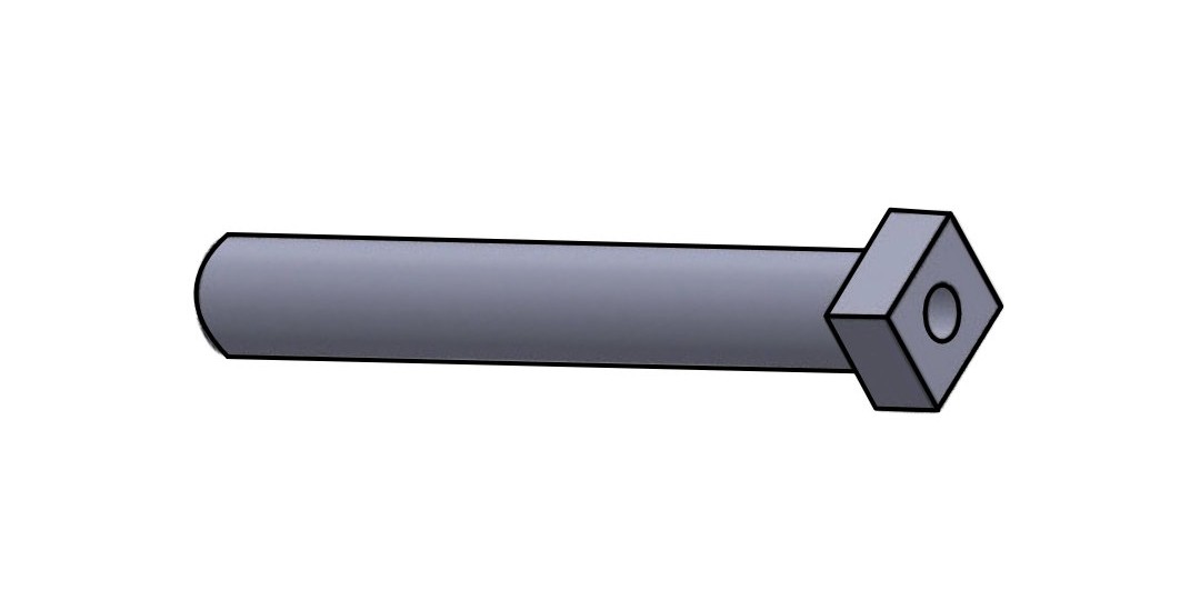
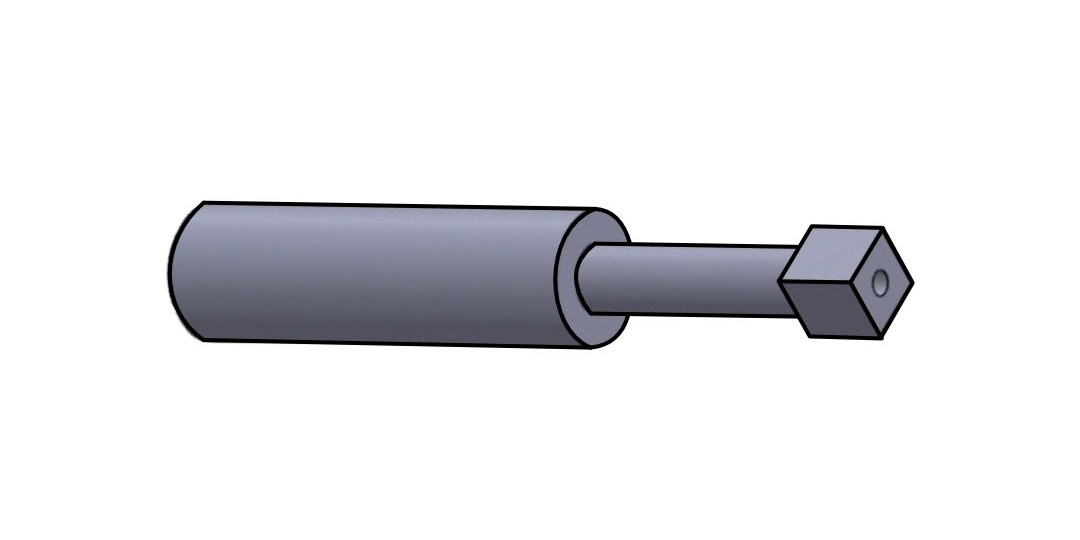
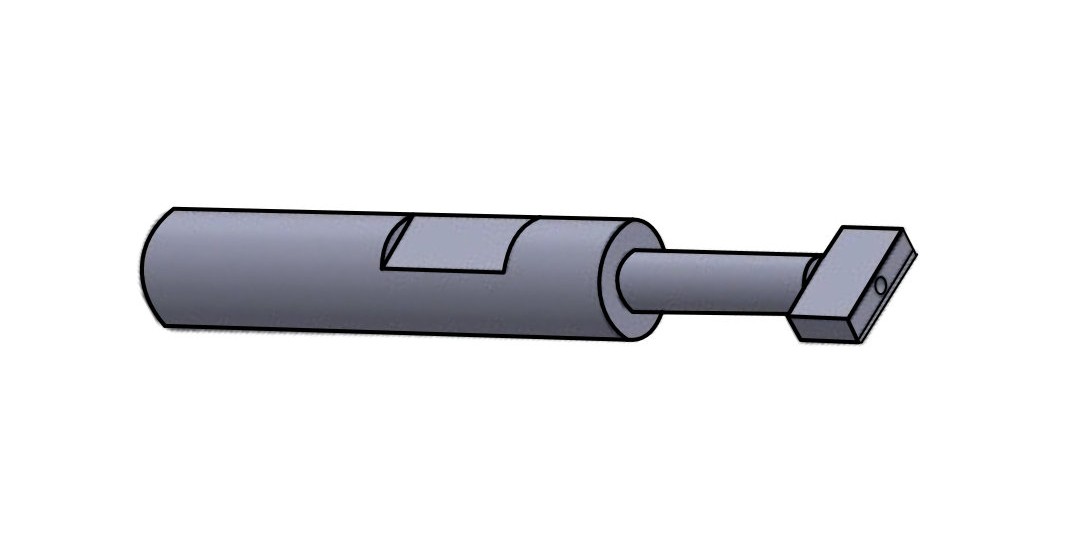
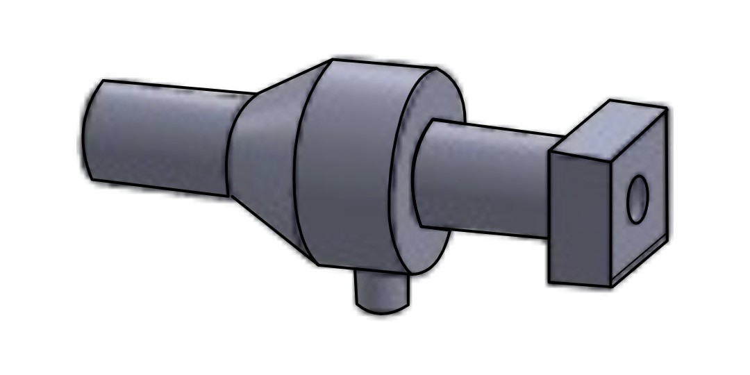
Four standard shank structures are available, covering straight, stepped, flat-sided and flanged mounting styles to match different equipment interfaces.
Tip Types
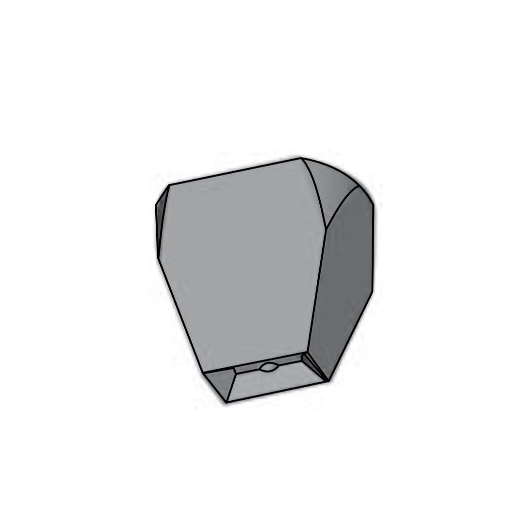
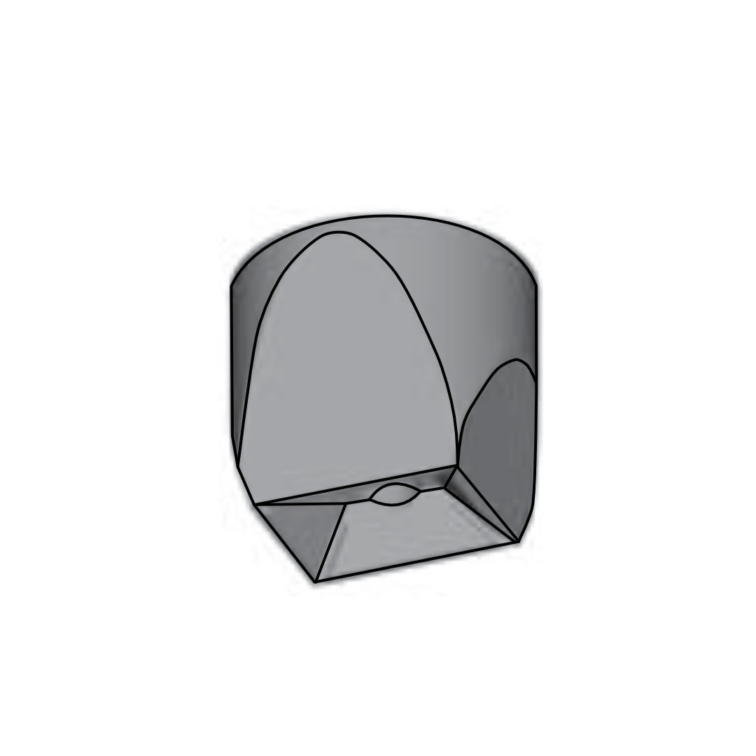
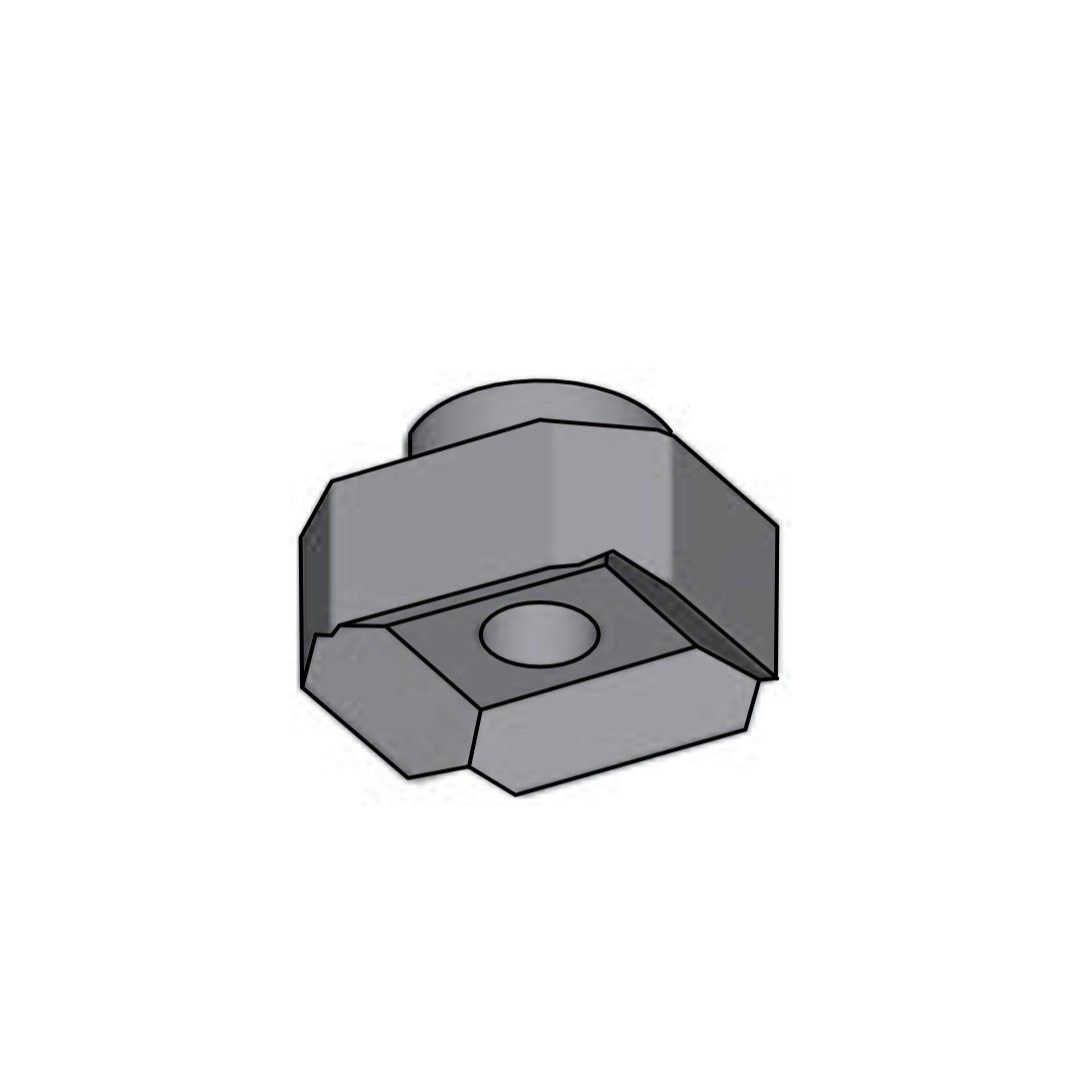
Two tip geometry families are available, each suited to a different die profile:
4 Sided Inverted Pyramid Die
2 Sided Inverted Channel Die
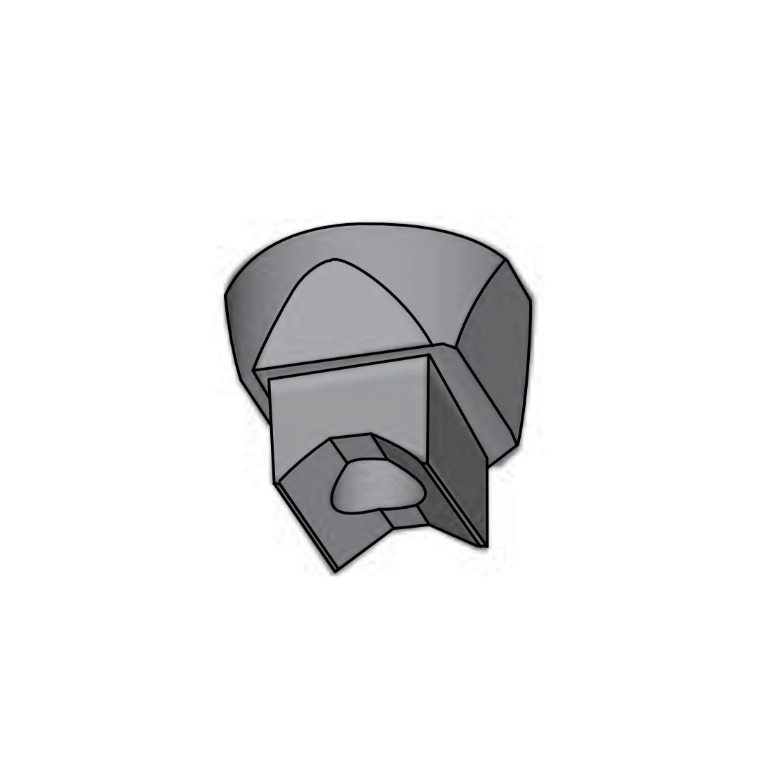
Tip structure selection depends on the die’s pickup contact geometry — send us your die drawing and we’ll confirm which tip type applies.
How to Order
Not Sure Which Tip Structure or Shank Fits Your Process?
Send us your die dimensions (length, width, thickness), equipment shank interface, and preferred tip geometry — our engineers will confirm the part number and recommend the right configuration.